Design and Quality (Ground Improvement Specialists)

The Design

  • The design comprises the assessment of bearing capacity, settlement, stability and liquefaction potential of a soil after Vibroflotation Ground Improvement.
    For Vibro Compaction the design is very straightforward :
    Assess the required improved soil strength and stiffness after compaction and calculate otherwise as for any unimproved soil. The only difficulty lies in the evaluation of the degree of compaction possible in different soils. This can only be assessed with extensive experience in local soil conditions and the use of appropriate sounding techniques.
    For stone columns the design is much more complex. Stone columns are a ground reinforcement, and their behavior is closely linked to the behavior of the soil surrounding the columns. Specific calculation methods for stone columns have been developed and calibrated using full scale tests, allowing stone columns to be designed with the same confidence as piles but with the advantage of better resistance to earthquake loads.

The graph shows the settlement reduction with different percentages of soil being replaced by stone columns.

 Screenshot of the DC software.

Reduction of Settlements

Based on Priebe’s design diagram and assuming 25 % of the soil being replaced by stone columns (factor A/Ac =4) and a friction angle for the column material of 40°, it follows that n = 2.6, i.e. a 2.6-fold reduction in settlements as compared to the unimproved ground. DC-Software and Vibroflotation Group have jointly developed a Windows® program called DC-Vibro. This software is based on the Priebe method including the depth factor. A free trial version of this software can be downloaded from the Internet on DC-Software’s site www.dc-software.de. With DC-Vibro any arrangement of structures can be input and for every cross-section, an individual multilayer soil model and varying column diameter over depth profile can be assumed.
A depth factor has been added to take into consideration the positive effect of larger confinement of the stone column with increased depth.

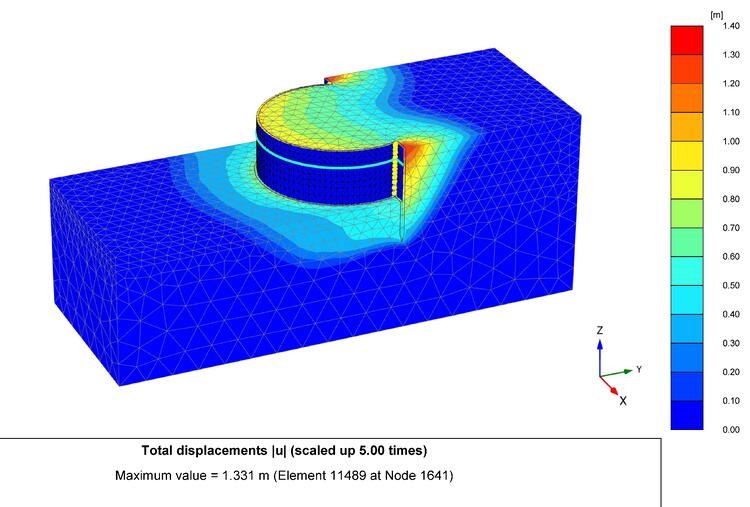
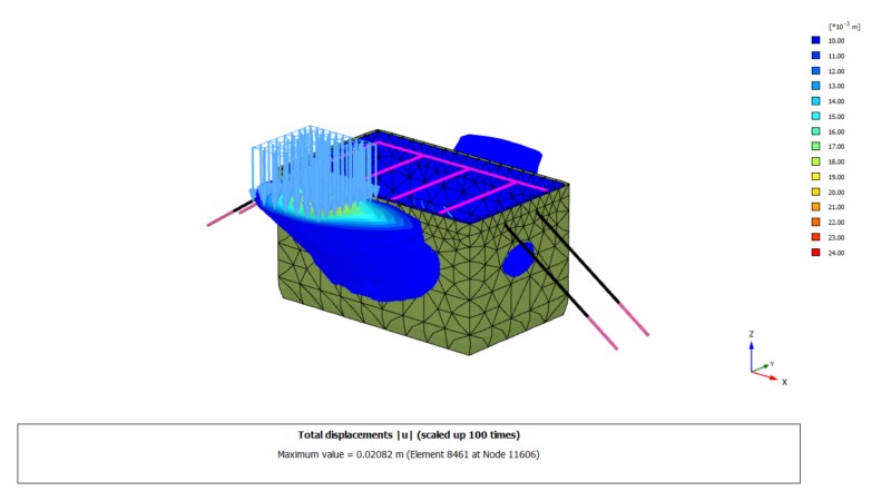
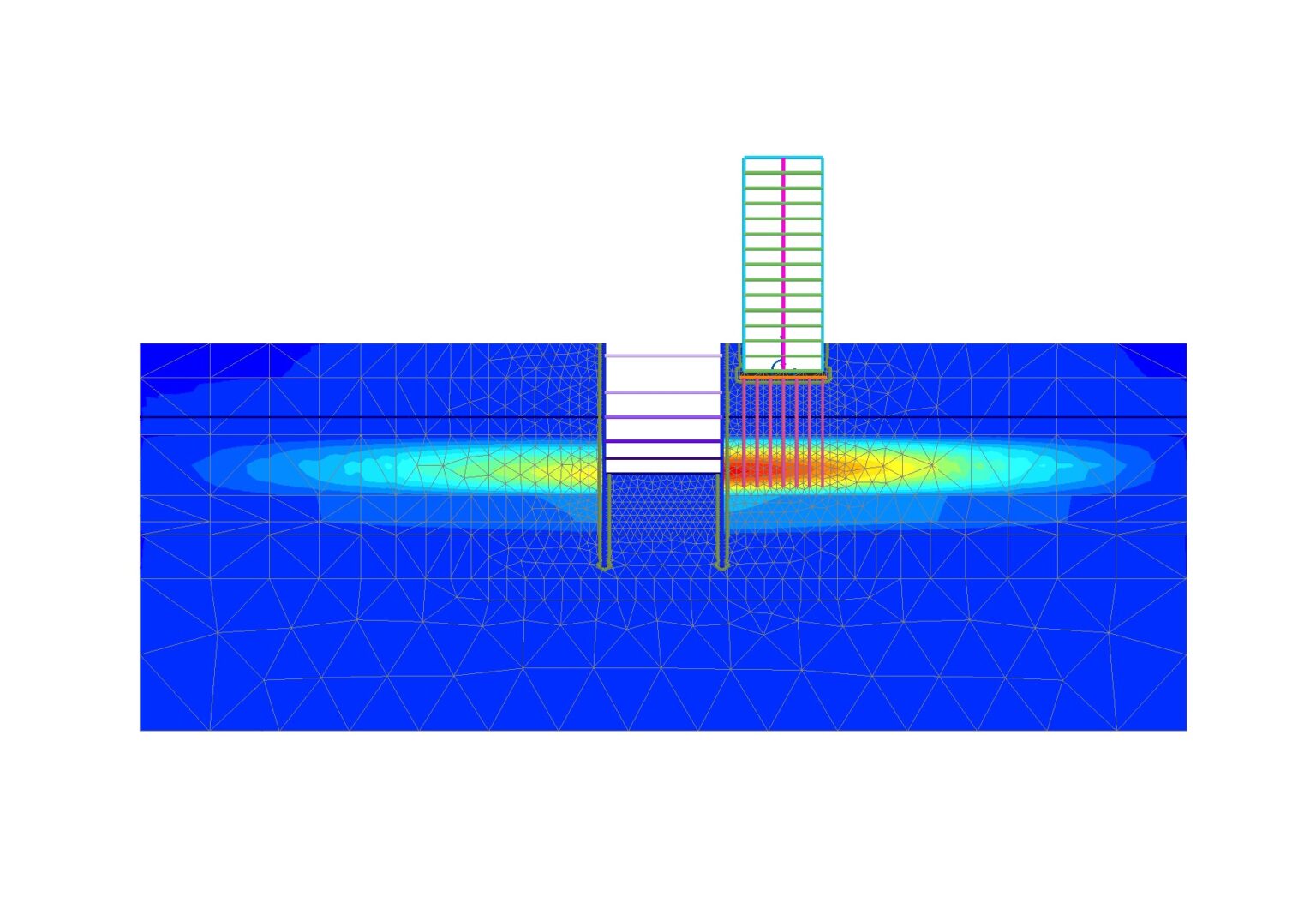
The screenshot (finite elements software: plaxis®) shows possible slope failure without stone columns.Safety factor against slope failure:

F = 1.06 

After slope stabilisation with stone columns: F = 1.60

Increase in Slope Stability

Stone columns have a threefold effect in soil :

Compaction of compatible layers.
Layers of clean sand and gravel and slightly silty sand (up to 20 % fines content) are compacted during the process of stone column installation.Reinforcement of the soil.
Column and soil form a reinforced matrix with instantly increased shear resistance and stiffness modulus. The high friction angle of the column material gives an immediate overall increase in shear strength to the composite of soil and column.Drainage.
The columns accelerate drainage (consolidation) of the cohesive soil, i.e. the columns work as vertical drains and thereby accelerate reduction of harmful excess pore pressures

Mitigation of Soil Liquefaction

The compaction of the in-situ soil is the most important positive effect of vibrocompaction or stone columns for the prevention of liquefaction in granular soil layers.

In soils with a silt content of over 10 % the most important effect of the stone column is the reduction of the total cyclic shear stress in the soil. The graph left shows that the required sounding resistance can be variable over depth as long as a proper consideration of the varying fines content is made. In order to achieve the same safety factor against liquefaction in an SM-ML a SPT blow count of 11 is sufficient, while in the clean sand a value of around 20 is required

Stone column construction should be closely monitored and design adapted to suit actual soil conditions.

The shear stress is partially taken over by the stone column

Stone columns reinforce and compact the soil. Liquefaction can be prevented.

Quality Assurance

GEO Civil Foundation engineering is the civil engineering discipline with the highest potential for variance between assumed behaviour and actual as-built behaviour. This stems from the large uncertainties in the characteristics of the building material, the in-situ soil. No matter how much field and laboratory exploration data is available, the unknowns and uncertainties will always be greater than for steel, concrete and other construction materials.

Detailed measurements and observations are therefore of paramount importance and an efficient quality assurance/control system is mandatory. Modern data acquisition systems intelligently combined with equipment built to allow for the exact measurement of process parameters (such as a precise gravel consumption by volume over depth) are now available.

Quality Control for Dry Bottom Feed Stone Columns
Digital quality control for dry bottom feed stone columns

In order to be able to print out column diameter variations with depth, it is necessary to measure precisely the volume of each gravel batch and the depth, at which it was placed in the ground.The Double Lock Gravel Pump is the optimal machine for an exact gravel volume control. This volume measurement is particularly useful for offshore (marine) stone column installation, where a visual control of the gravel consumption or gravel loss on the seabed is not possible.
Quality Assurance for Vibro Compaction 
Quality control for a Vibro Compaction consists of the following steps :
  • Before compaction
    Determine Pre-Compaction CPT or SPT sounding.Establish the Pre-Compaction ground level of the compaction area.
  • During compaction
    Record ampere variation with depth during every compaction point installation.

Analog data logger
showing ampere over time (blue) and depth over time (red).

CPT results before and after compaction. The non compacted layers result from a silt content exceeding 10 %.

Digital data logger showing depth variation with time on the left and amperage variation with time on the right. (two vibroflots – “tandem” operation)

  • After compaction
    Determine Post-Compaction CPT or SPT sounding and adjust for Post Compaction ground levels.

Post-compaction cone penetration tests (CPT) compared to the pre-compaction test and showing the improvement achieved versus the specified minimum performance line.

Vibro Compaction

Typical requirement for Post Compaction CPT sounding

The Aging Effect

An increase of CPT result is clearly visible after a waiting period of eleven days in comparison to only five days (sand compaction on Hong Kong Airport project).

Piling & Shoring Design

Our design team has expert engineers for the design of Shoring / Piling systems. We have engineers who have vast experience in geotechnical investigation and engineering giving them an edge in the analysis of soil conditions. Parameters such as surcharge loads, soil properties,and water pressure are carefully assessed to find the optimum design for the system. The appropriate shoring system is proposed based on the soil conditions as well as neighbouring structures.
Geotechnical contractor , Soil Improvement
Soil Improvement (Vibro Compaction / Stone Columns) ,(Design and Build)
all types of bored and driven piling works , all types of shoring works ,Soldier Pile Shoring ,
Secant Wall , Diaphragm Wall , Contiguous Wall , Soldier Piles ,Sheet Piles , Steel H-Beams, Shoring Plates
Micro Piles and Ground Anchors
Marine Works:Sheet piling of Cofferdams ,Jetties, Wharves